
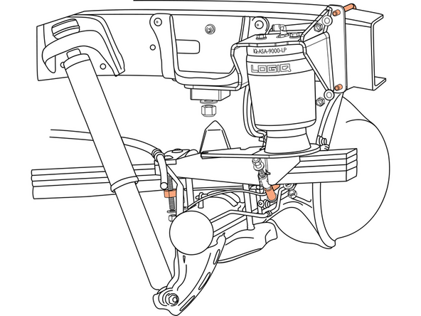
Introduction
In this guide we’ll show you how to properly install the ReadyAIR Load Leveling Kit for the 2007-2021 Toyota Tundra.
READ INSTRUCTIONS THOROUGHLY AND COMPLETELY BEFORE INSTALLATION.
INSTALLATION BY A CERTIFIED PROFESSIONAL MECHANIC IS HIGHLY RECOMMENDED.
LOGIQTM IS NOT RESPONSIBLE FOR ANY DAMAGE OR FAILURE RESULTING FROM IMPROPER INSTALLATION.
Note: If your ReadyAIR product has a damaged or missing part, please contact customer service directly at 800-549-4620 and a new replacement part will be sent to you immediately. For warranty issues, please return to the place of installation and contact LOGIQ via email at tech@LOGIQair.com.
WARRANTY
LOGIQTM provides a limited lifetime warranty to the original purchaser of products, that the product be free from defects in workmanship and materials when used on cars and trucks as specified by LOGIQTM and under normal operating conditions. This warranty is subject to the requirements and exclusions set forth in the full Limited Warranty and Return Policy that is available at logiqair.com/warranty. Air compressors are a wearing component and are covered by a 2-year warranty from the date of purchase. The warranty does not provide coverage for abuse, operation in a manner not consistent with the product’s design, or damage resulting from exposure to the elements.
WARNINGS & DISCLAIMERS
By installing this product you acknowledge that the suspension of this vehicle has been modified. As a result, this vehicle may handle differently than that of factory-equipped vehicles. As with any vehicle, extreme care must be used to prevent loss of control or roll-over during sharp turns or abrupt maneuvers. Always wear seat belts, and drive safely, recognizing that reduced speeds and specialized driving techniques may be required. Failure to drive this vehicle safely may result in serious injury or death. Do not drive this vehicle unless you are familiar with its unique handling characteristics and are confident of your ability to maintain control under all driving conditions. Some modifications (and combinations of modifications) are not recommended and may not be permitted in your state. Consult your owner’s manual, the instructions accompanying this product, and state laws before undertaking these modifications. You are responsible for the legality and safety of the vehicle you modify using these components.
| APPLICATION NOTES |
| TRUCK COMPATIBILITY |
| NOT COMPATIBLE WITH TRD PRO |
| OTHER TRD MODELS ARE COMPATIBLE |
| ONLY FOR USE WITH FACTORY LEAF SPRINGS |
| 5TH WHEEL COMPATIBLITY |
| B&W BWGNRK1257 |
| CURT C60667 |
Tools
Parts
- Driver Side Air Spring Assembly
- Passenger Side Air Spring Assembly
- 3/8"-16 x 3.75" Hex Head Bolt × 4
- 3/8"-16 x 4" Carriage Bolt × 4
- 3/8"-16 x 1.5" Hex Head Bolt
- 3/8"-16 x 5" Hex Head Bolt
- 3/8"-16 x 4.25" U-Bolt 5.8" CTC
- 3/8"-16 Nylon Locking Nut × 12
- 3/8" Flat Washer × 18
- 5/8"-11 x 2" Carriage Bolt Grade 8 × 2
- 5/8"-11 Nylon Locking Nut Grade 8 × 2
- 5/8" Flat Washer × 2
- 5/8" Rectangle Carriage Bolt Washer × 2
- Passenger Side Air Spring Upper Frame Spacer
- Passenger Side Air Spring Upper Frame Clamp
- Air Spring Lower Strap 3.0" CTC × 2
- Leaf Spring Bottom Clamp × 2
- E-Brake Relocation Bracket
- 5/8" ID Adel Clamp
- 1/4"-20 x 1" Socket Head Cap Screw
- 1/4"-20 Nylon Locking Nut
- 1/4" Flat Washer × 2
- M8-1.25 x 25mm Hex Head Bolt × 2
- M8-1.25 Nylon Locking Nut
- M8 Flat Washer × 3
- 8" Zip Tie × 16
- Inflation Valve to 1/4" PTC Fitting × 2
- 16' Roll of 1/4" Air Line
-
-
Note original ride height measurement from center of rear fender arch to ground.
-
Safely lift truck and support with jack stands under axle. Remove the rear wheels.
-
-
-
Unbolt the emergency brake cable brackets on both sides of the truck.
-
-
-
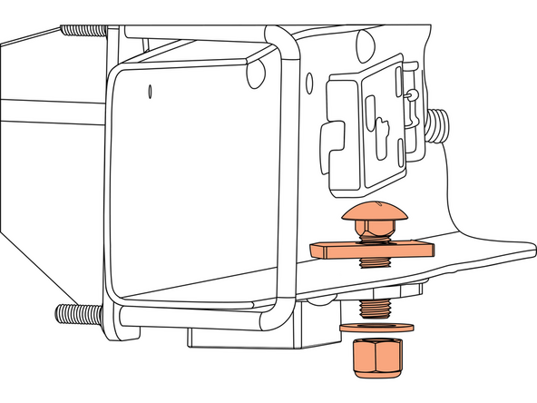
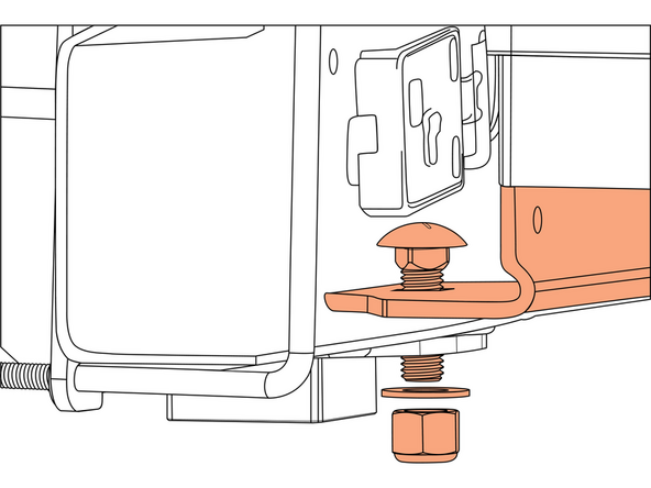
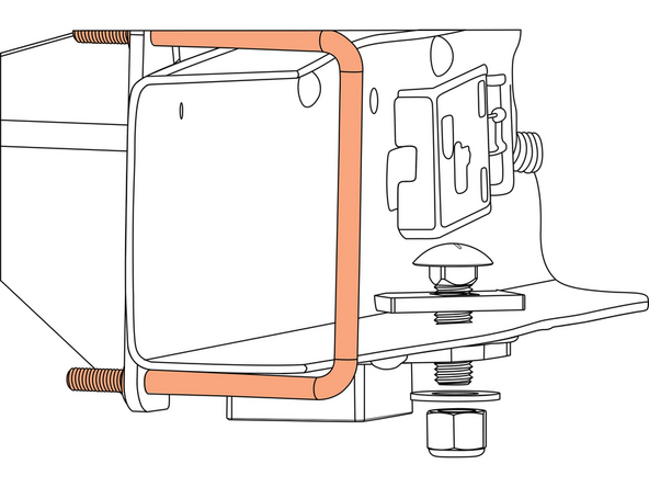
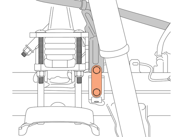
Install the supplied 5/8" carriage bolt and carriage bolt washer through the hole in the frame and the upper bracket.
-
If using with an aftermarket 5th wheel bracket, install the carriage bolt WITHOUT the carriage bolt washer and instead through both the 5th wheel bracket and the upper bracket.
-
Snug the carriage bolt to hold the assembly in place, while allowing room for the upper bracket to move to install the other fasteners.
-
-
-
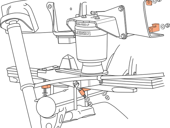
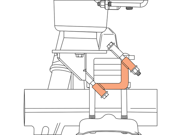
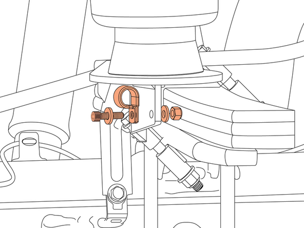
Passenger assembly will be fastened with 3/8" hardware and the lower bracket clamps in the orientation shown.
-
Install the upper 3/8" bolt with washers, nut and frame spacer. Ensure it is sitting flush against the frame. Install the lower 3/8" bolt with washers, nut and frame clamp. Ensure the clamp is sitting against the frame.
-
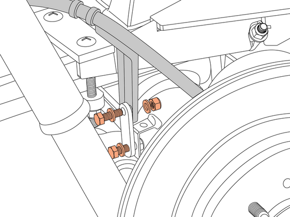
Secure the lower bracket to the leaf spring with the supplied 3/8" hardware and clamps. Make sure the bracket cut-outs are aligned with the U-bolt saddle, and the leaf spring bottom clamp is oriented correctly. Snug the hardware.
-
-
-
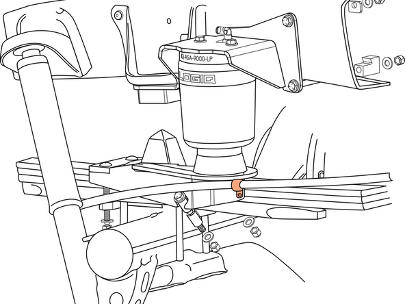
Driver assembly will be fastened with the U-bolt and lower bracket clamps in the orientation shown.
-
Install the 3/8" U-bolt with washers & nuts so that it is clamping around the frame.
-
Secure the lower bracket to the leaf spring with the supplied 3/8" hardware and clamps. Make sure the bracket cut-outs are aligned with the U-bolt saddle, and the leaf spring bottom clamp is oriented correctly. Snug the hardware.
-
-
-
Once all fasteners are installed, use provided E-brake relocation bracket and install on driver side with provided M8 hardware. Torque to 8 FT. LB.
-
-
-
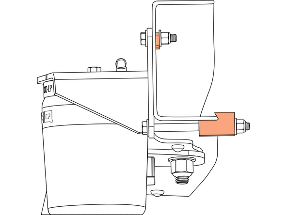
On the passenger side, bend and remove the factory E-brake bracket from the cable and fasten to the lower air spring bracket using the provided 5/8" Adel clamp and 1/4" hardware. Torque to 7 FT. LB.
-
Ensure that the E-brake cable has adequate clearance and is not making contact with any components.
-
-
-
Torque all 3/8" hardware to 20 FT. LB.
-
Torque all 5/8" hardware to 110 FT. LB.
-
-
-
When used with an on-board air management system, refer to the on-board air management system installation instructions before routing the air lines.
-
When not using an on-board air management system, mount inflation valves at desired location using 5/16" drill bit
-
Route air line from each inflation valve to each air fitting on both of the air spring assemblies. Avoid hot exhaust and sharp edges. Cut air line square and free from burrs with air line cutter or razor blade!
-
-
-
Check for leaks at fittings with soapy water.
-
Check tire clearance to air spring (must be more than 1")
-
Verify all fasteners are torqued properly.
-
Verify at least 10 psi in air spring before driving.
-


Congratulations! You have successfully installed your new ReadyAIR kit!
If you have any questions or concerns, please contact LOGIQ at 800-549-4620.
Congratulations! You have successfully installed your new ReadyAIR kit!
If you have any questions or concerns, please contact LOGIQ at 800-549-4620.