
Introduction
In this guide we’ll show you how to properly install the ReadyAIR load leveling kit for the 2013+ RAM 3500.
READ INSTRUCTIONS THOROUGHLY AND COMPLETELY BEFORE INSTALLATION.
INSTALLATION BY A CERTIFIED PROFESSIONAL MECHANIC IS HIGHLY RECOMMENDED.
LOGIQTM IS NOT RESPONSIBLE FOR ANY DAMAGE OR FAILURE RESULTING FROM IMPROPER INSTALLATION.
Note: If your ReadyAIR product has a damaged or missing part, please contact customer service directly at 800-549-4620 and a new replacement part will be sent to you immediately. For warranty issues, please return to the place of installation and contact LOGIQ via email at tech@LOGIQair.com.
WARRANTY
LOGIQTM provides a limited lifetime warranty to the original purchaser of products, that the product be free from defects in workmanship and materials when used on cars and trucks as specified by LOGIQTM and under normal operating conditions. This warranty is subject to the requirements and exclusions set forth in the full Limited Warranty and Return Policy that is available at logiqair.com/warranty. Air compressors are a wearing component and are covered by a 2-year warranty from the date of purchase. The warranty does not provide coverage for abuse, operation in a manner not consistent with the product’s design, or damage resulting from exposure to the elements.
WARNINGS & DISCLAIMERS
By installing this product you acknowledge that the suspension of this vehicle has been modified. As a result, this vehicle may handle differently than that of factory-equipped vehicles. As with any vehicle, extreme care must be used to prevent loss of control or roll-over during sharp turns or abrupt maneuvers. Always wear seat belts, and drive safely, recognizing that reduced speeds and specialized driving techniques may be required. Failure to drive this vehicle safely may result in serious injury or death. Do not drive this vehicle unless you are familiar with its unique handling characteristics and are confident of your ability to maintain control under all driving conditions. Some modifications (and combinations of modifications) are not recommended and may not be permitted in your state. Consult your owner’s manual, the instructions accompanying this product, and state laws before undertaking these modifications. You are responsible for the legality and safety of the vehicle you modify using these components.
| APPLICATION NOTES |
| TRUCK COMPATIBLITIY |
| NOT COMPATIBLE ON TRUCKS EQUIPPED WITH FACTORY AIR SUSPENSION |
| 5TH WHEEL COMPATIBILITY |
| BWGNRK1314 |
| BWRVK2605 |
| CURT C60626 |
| CURT C16430-204 |
| DRAW-TITE 9466 |
| REESE RP50085-58 |
| REESE RP56010-53 |
Tools
Parts
- Driver Side Air Spring Assembly
- Passenger Side Air Spring Assembly
- Bump Stop Spacer × 2
- Upper Bracket Shim × 12
- M10-1.5 x 100mm Hex Head Bolt × 4
- M10 Flat Washer × 4
- 1/2"-13 Axle U-Bolt × 2
- 1/2" Flat Washer × 4
- 1/2"-13 Nylon Locking Nut × 4
- E-Brake Cable Relocation Bracket Base
- E-Brake Cable Relocation Bracket Cap
- 1/4"-20 x 1.75" Socket Head Cap Screw
- 1/4"-20 x 1" Socket Head Cap Screw
- 1/4"-20 x .50" Socket Head Cap Screw
- 2mL Red Threadlocker Packet
- Heat Wrap
- Hose Clamp × 2
- 8" Zip Tie × 16
- Inflation Valve to 1/4" PTC Fitting × 2
- 16' Roll of 1/4" Air Line
-
-
Note original ride height measurement from center of rear fender arch to ground.
-
Safely lift truck and support with jack stands under axle. Remove the rear wheels.
-
-
-
Un-bolt bump stops from both sides of the truck using a 16mm socket.
-
-
-
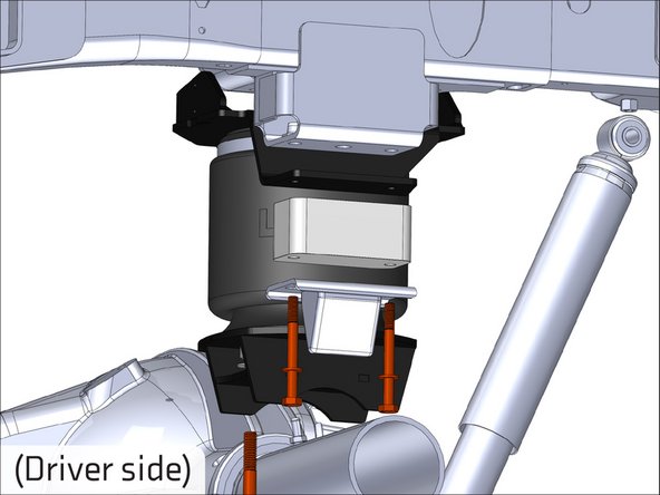
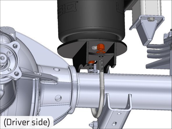
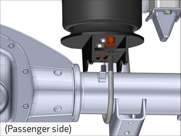
Attach the upper bracket, bump stop spacer, and factory bump stop to the bump stop perch with the supplied M10 bolts and washers as shown.
-
Apply some of the provided thread locker to each bolt before installing.
-
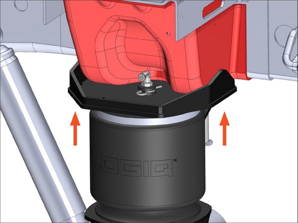
Before snugging the bolts, push the upper bracket up so it is in contact with the crossmember.
-
Fill in the gap between the upper bracket and the bump stop perch with as many of the provided shims as necessary.
-
Repeat process for passenger side.
-
-
-
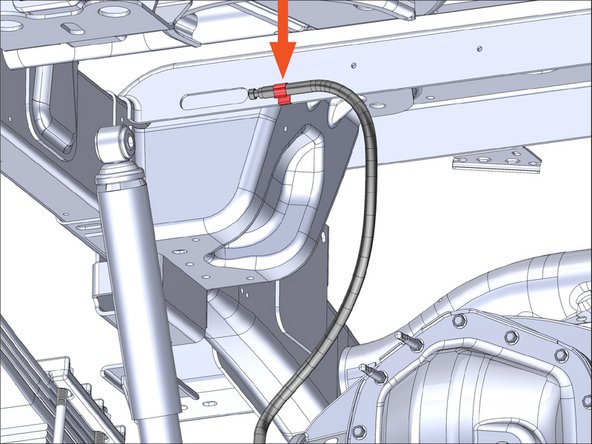
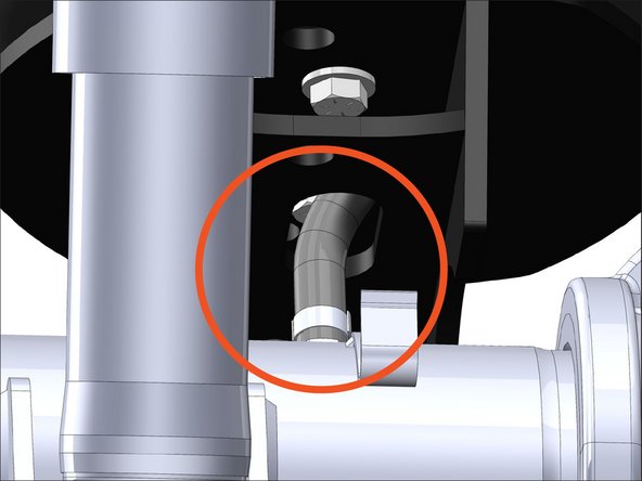
Detach the differential breather line from its anchor point on the frame shown. (On the driver side of the axle)
-
Route the breather line through the slot in the middle of the driver side lower bracket.
-
-
-
Attach the lower bracket to the axle using the supplied U-bolt, washers and nuts.
-
Be sure to use a wrench and not a socket to snug the U-bolt nuts.
-
Re-attach the breather line anchor point to its original location on the frame once the driver side lower bracket is secured.
-
-
-
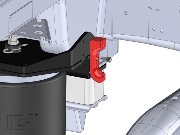
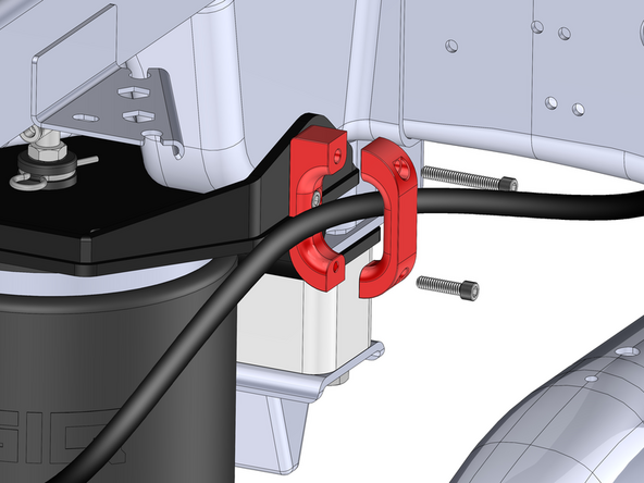
Install the E-brake relocation bracket on the driver side upper bracket using the supplied 1/4" hardware.
-
The base piece of the bracket gets attached to the upper bracket first with the .50" long screw. Torque the screw to 7 FT. LB. using a 3/16" allen socket.
-
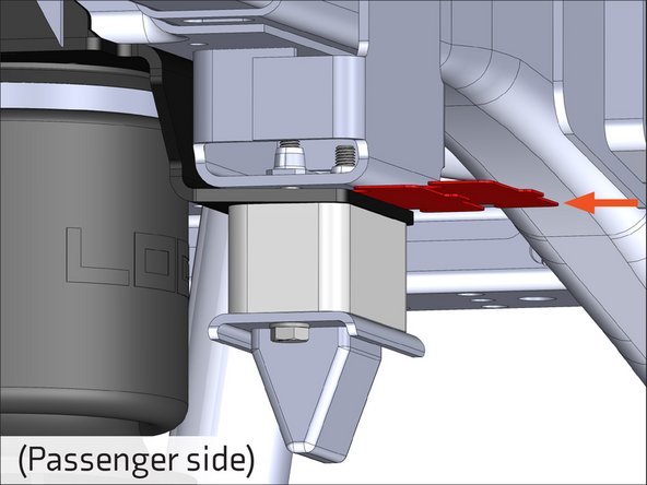
Route the E-brake cable through the middle of the base bracket. Secure the cap piece of the bracket to the base with the other two 1/4" screws (longer of the two goes in the top hole) to capture the E-brake cable.
-
-
-
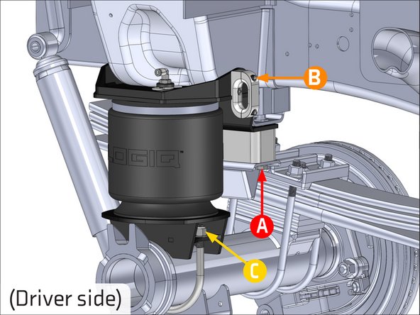
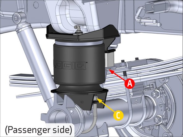
A: Torque Upper bracket first. Torque the M10 bolts to 40 FT. LB. using a 17mm socket.
-
B: Torque the rest of the E-brake relocation bracket hardware to 7 FT. LB. using a 3/16" allen socket.
-
C: Torque lower bracket hardware to 75 FT. LB. using a 3/4" crowsfoot.
-
-
-
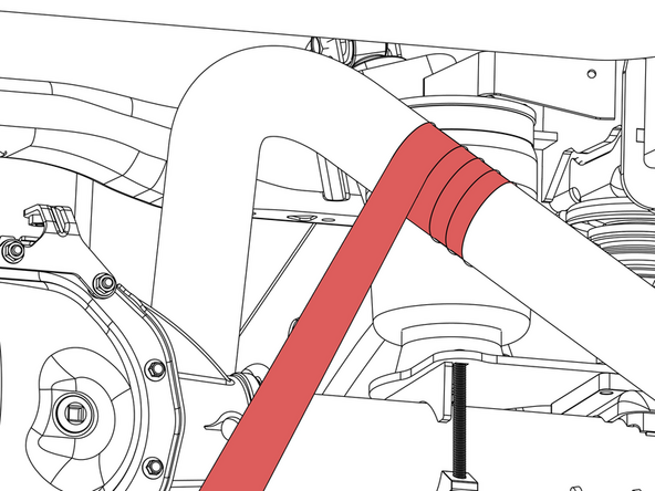
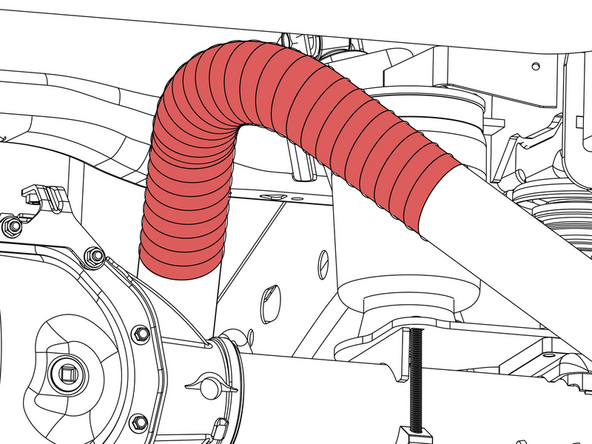
Begin 12 inches behind the air spring and wrap toward the front of the vehicle.
-
Ensure you have overlap that is about half the thickness of the heat wrap like shown.
-
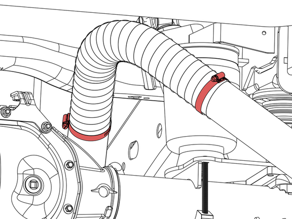
Once the whole roll has been wrapped onto the exhaust, attach the provided hose clamps to each end of the wrap as shown.
-
Ensure the wrap extends at-least 12 inches in front and behind the air spring (more is better if there is enough wrap).
-
Trim any excess clamp stick-out with a pair of metal snips.
-
-
-
When used with an on-board air management system, refer to the on-board air management system installation instructions before routing the air lines.
-
When not using an on-board air management system, mount inflation valves at desired location using 5/16" drill bit
-
Route air line from each inflation valve to each air fitting on both of the air spring assemblies. Avoid hot exhaust and sharp edges. Cut air line square and free from burrs with air line cutter or razor blade!
-
-
-
Check for leaks at fittings with soapy water.
-
Verify all fasteners are torqued properly.
-
Verify at least 10 psi in air spring before driving.
-

Congratulations! You have successfully installed your new ReadyAIR kit!
If you have any questions or concerns, please contact LOGIQ at 800-549-4620.
Congratulations! You have successfully installed your new ReadyAIR kit!
If you have any questions or concerns, please contact LOGIQ at 800-549-4620.