
Introduction
In this guide we’ll show you how to properly install the ReadyAIR Load Leveling Kit for the 2023+ Ford F-250/F-350/F-450.
READ INSTRUCTIONS THOROUGHLY AND COMPLETELY BEFORE INSTALLATION.
INSTALLATION BY A CERTIFIED PROFESSIONAL MECHANIC IS HIGHLY RECOMMENDED.
LOGIQTM IS NOT RESPONSIBLE FOR ANY DAMAGE OR FAILURE RESULTING FROM IMPROPER INSTALLATION.
Note: Not compatible with Platinum, Limited, or any trucks equipped with rear height sensors. (Expected compatibility Oct 2023)
If your ReadyAIR product has a damaged or missing part, please contact customer service directly at 800-549-4620 and a new replacement part will be sent to you immediately. For warranty issues, please return to the place of installation and contact LOGIQ via email at tech@LOGIQair.com.
WARRANTY
LOGIQTM provides a limited lifetime warranty to the original purchaser of products, that the product be free from defects in workmanship and materials when used on cars and trucks as specified by LOGIQTM and under normal operating conditions. This warranty is subject to the requirements and exclusions set forth in the full Limited Warranty and Return Policy that is available at logiqair.com/warranty. Air compressors are a wearing component and are covered by a 2-year warranty from the date of purchase. The warranty does not provide coverage for abuse, operation in a manner not consistent with the product’s design, or damage resulting from exposure to the elements.
WARNINGS & DISCLAIMERS
By installing this product you acknowledge that the suspension of this vehicle has been modified. As a result, this vehicle may handle differently than that of factory-equipped vehicles. As with any vehicle, extreme care must be used to prevent loss of control or roll-over during sharp turns or abrupt maneuvers. Always wear seat belts, and drive safely, recognizing that reduced speeds and specialized driving techniques may be required. Failure to drive this vehicle safely may result in serious injury or death. Do not drive this vehicle unless you are familiar with its unique handling characteristics and are confident of your ability to maintain control under all driving conditions. Some modifications (and combinations of modifications) are not recommended and may not be permitted in your state. Consult your owner’s manual, the instructions accompanying this product, and state laws before undertaking these modifications. You are responsible for the legality and safety of the vehicle you modify using these components.
| APPLICATION NOTES | |
| TRUCK COMPATIBILITY | |
| ALL TRUCK VARIATIONS WITH OVERLOAD SPRINGS | |
| 5TH WHEEL COMPATIBILITY | |
| OEM 5TH WHEEL | |
| BW GNRK1123 | |
Tools
Parts
- Driver Side Air Spring Assembly
- Passenger Side Air Spring Assembly
- 5/8"-11 x 3.5" Hex Head Bolt Grade 8 × 4
- 5/8"-11 x 4" Hex Head Bolt Grade 8 × 4
- 5/8" Flat Washer × 4
- 5/8" Split Lock Washer × 4
- Air Spring Lower Strap 3.5" CTC × 4
- 3/8"-16 x 4" Carriage Bolt × 8
- 3/8"-16 Nylock Nut × 8
- 3/8" Flat Washer × 8
- Bump Stop Spacer × 2
- M10-1.5 x 16mm Hex Head Bolt × 2
- 2mL Red Threadlocker Packet
- Center Pin Spacer × 2
- M18 Axle U-Bolt Spacer × 8
- 1/2"-20 x 4" Leaf Spring Center Pin × 2
- 1/2" Flat Washer × 2
- 1/2" Split Lock Washer × 2
- 1/2"-20 Hex Nut × 2
- 7/16"-20 x 3.5" Leaf Spring Center Pin × 2
- 7/16" Flat Washer × 2
- 7/16" Split Lock Washer × 2
- 7/16"-20 Hex Nut × 2
- 8" Zip Tie × 16
- Inflation Valve to 1/4" PTC Fitting × 2
- 16' Roll of 1/4" Air Line
-
-
Note original ride height measurement from center of rear fender arch to ground.
-
Safely lift truck and support with jack stands under axle. Remove the rear wheels.
-
If your truck is equipped with the extended bump stop shown - please stop and contact LOGIQTM customer service before finishing installation.
-
-
-
Spray the factory center pin nuts and axle U-bolt nuts with penetrating oil.
-
One side at a time, remove the center pin nut and factory axle U-bolts.
-
Remove the overload spring and overload spacer block.
-
Reinstall factory U-bolt saddle and install the supplied Center Pin Spacer with the correct size flat washer, split washer, and center pin nut.
-
Reinstall factory U-bolts with the supplied Axle U-bolt Spacers between the axle cradle and the U-bolt nuts.
-
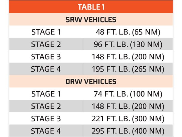
Torque the U-bolt nuts in a cross pattern in 4 stages to the specifications shown in TABLE 1 below.
-
Torque the center pin nut to 35 FT. LB.
-
If your factory center pin got damaged during the overload spring removal process refer to the Alternate Overload Step.
-
-
-
Insert wisdom here.
-
-
-
If your factory center pin was damaged, then you will replace it with the supplied shorter replacement pin.
-
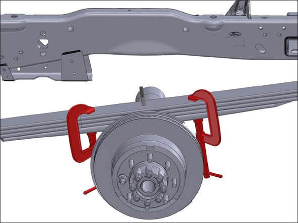
Clamp the leafs together with C-clamps front and rear as shown. Then jack the frame of the vehicle up until you have about 6 inches of working space between the bottom of the leaf pack and the top of the axle pad.
-
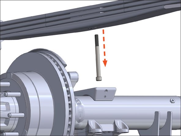
Remove the factory center pin from the leaf pack by driving it out from the top with a punch.
-
Install the new shorter leaf pack center pin that matches the diameter of the factory center pin (either 7/16" or 1/2").
-
Lower the frame so that the weight of the vehicle is sitting back on the axle.
-
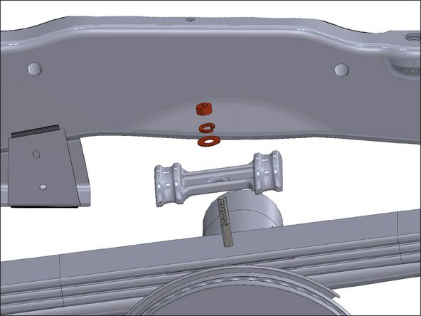
Make sure that the head of the center pin properly aligns with the hole in the axle pad.
-
Reinstall the factory U-bolt saddle with correct size flat washer, split washer, and center pin nut.
-
Please refer to the last part of STEP 2 for U-bolt re-installation instructions and torque specs for the U-bolt nuts and center pin nut.
-
-
-
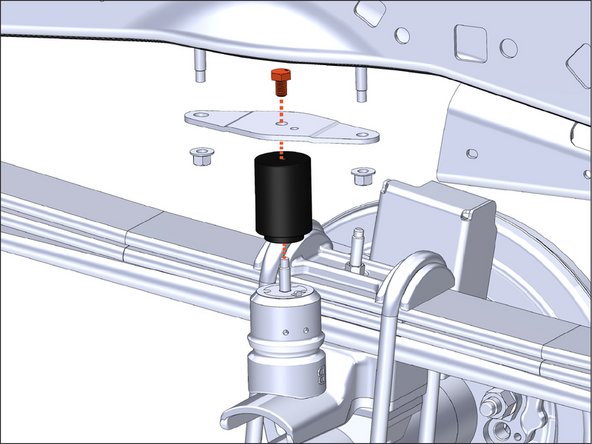
Unbolt factory bump stop using a 15mm socket.
-
Reinstall factory bump stops with provided aluminum spacer and longer M10 bolt.
-
Torque the M10 bolt to 15 FT. LB.
-
Reinstall the factory bump stop bracket to the frame.
-
Repeat for passenger side.
-
-
-
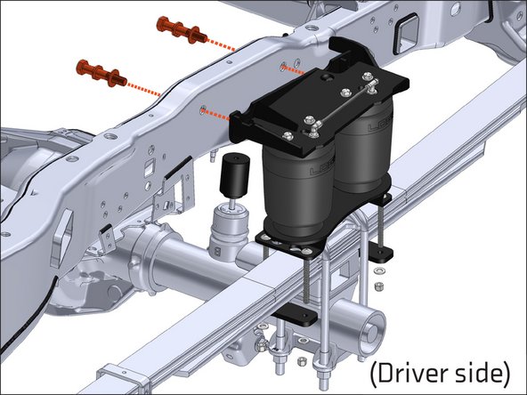
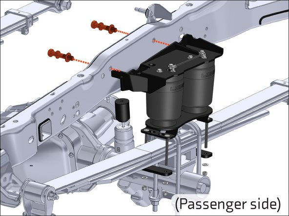
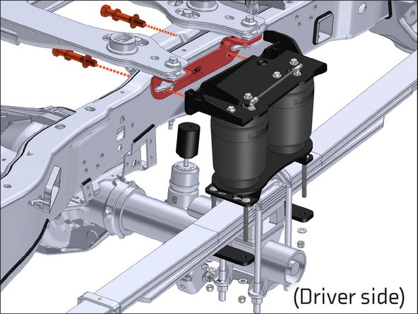
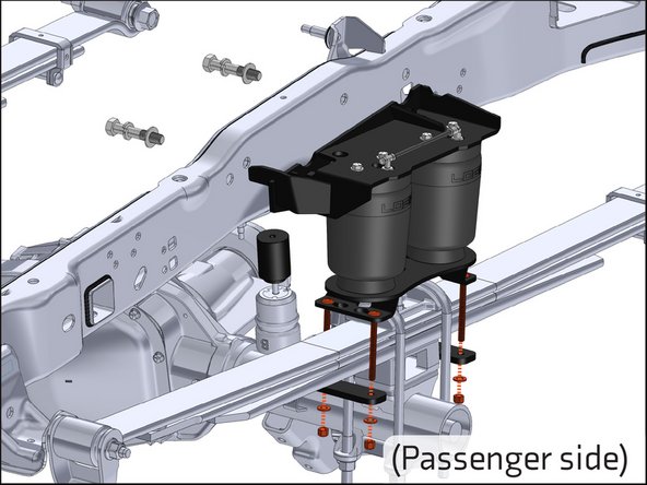
Use the supplied 3.5" long Grade 8 5/8" bolts, with split washers and flat washers, to attach the upper air spring bracket to the outside of the frame, through the factory sleeved holes. Snug hardware.
-
Repeat for passenger side.
-
-
-
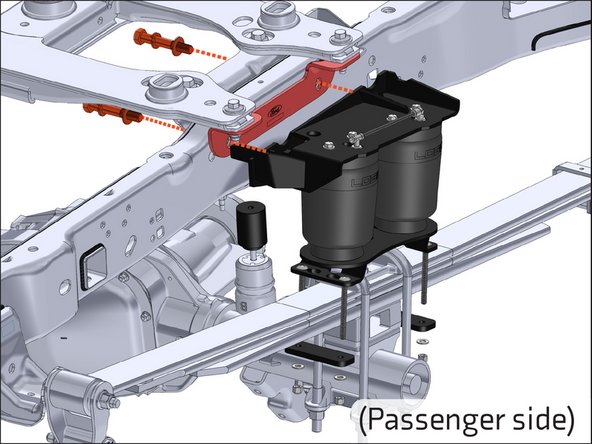
First remove the 5th wheel frame mounting hardware.
-
Use the supplied 4" long Grade 8 5/8" bolts, with split washers and flat washers, to attach the upper air spring bracket to the outside of the hitch, through the factory hitch mounting holes. Snug hardware.
-
Repeat for passenger side.
-
-
-
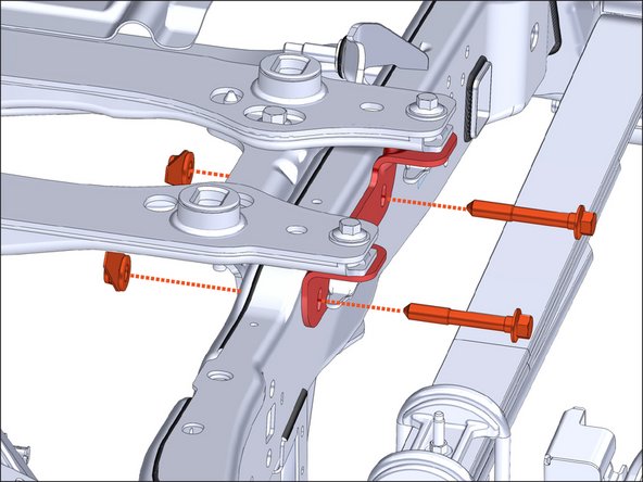
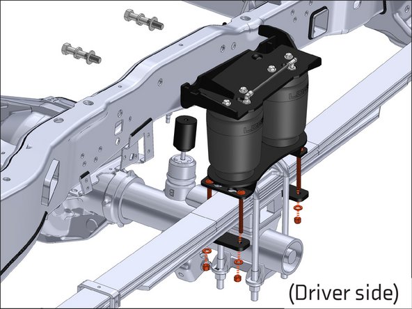
Use the supplied 3/8" hardware and leaf spring straps to attach the lower air spring bracket to the leaf spring.
-
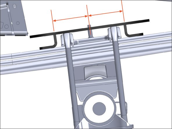
Make sure that the lower bracket is centered over the U-bolt saddle.
-
Repeat for passenger side.
-
-
-
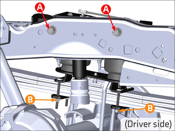
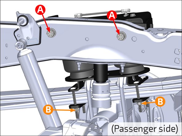
A: Torque the 5/8" hardware to 150 FT. LB.
-
B: Torque the 3/8" hardware to 20 FT. LB.
-
-
-
When used with an on-board air management system, refer to the on-board air management system installation instructions before routing the air lines.
-
When not using an on-board air management system, mount inflation valves at desired location using 5/16" drill bit.
-
Route air line from each inflation valve to each air fitting tee on both of the air spring assemblies. Avoid hot exhaust and sharp edges. Cut air line square and free from burrs with air line cutter or razor blade!
-
-
-
Check for leaks at fittings with soapy water.
-
Check tire clearance to air springs (more than 1").
-
Verify all fasteners are torqued properly.
-
Verify at least 10psi in air springs before driving.
-


Congratulations! You have successfully installed your new ReadyAIR kit!
If you have any questions or concerns, please contact LOGIQ at 800-549-4620.
Congratulations! You have successfully installed your new ReadyAIR kit!
If you have any questions or concerns, please contact LOGIQ at 800-549-4620.