
Introduction
In this guide we’ll show you how to properly install your replacement AirIQ ECU Module.
READ INSTRUCTIONS THOROUGHLY AND COMPLETELY BEFORE INSTALLATION.
INSTALLATION BY A CERTIFIED PROFESSIONAL MECHANIC IS HIGHLY RECOMMENDED.
LOGIQTM IS NOT RESPONSIBLE FOR ANY DAMAGE OR FAILURE RESULTING FROM IMPROPER INSTALLATION.
Note: If your ReadyAIR product has a damaged or missing part, please contact customer service directly at 800-549-4620 and a new replacement part will be sent to you immediately. For warranty issues, please return to the place of installation and contact LOGIQ via email at tech@LOGIQair.com.
WARRANTY
LOGIQTM provides a limited lifetime warranty to the original purchaser of products, that the product be free from defects in workmanship and materials when used on cars and trucks as specified by LOGIQTM and under normal operating conditions. This warranty is subject to the requirements and exclusions set forth in the full Limited Warranty and Return Policy that is available at logiqair.com/warranty. Air compressors are a wearing component and are covered by a 2-year warranty from the date of purchase. The warranty does not provide coverage for abuse, operation in a manner not consistent with the product’s design, or damage resulting from exposure to the elements.
WARNINGS & DISCLAIMERS
By installing this product you acknowledge that the suspension of this vehicle has been modified. As a result, this vehicle may handle differently than that of factory-equipped vehicles. As with any vehicle, extreme care must be used to prevent loss of control or roll-over during sharp turns or abrupt maneuvers. Always wear seat belts, and drive safely, recognizing that reduced speeds and specialized driving techniques may be required. Failure to drive this vehicle safely may result in serious injury or death. Do not drive this vehicle unless you are familiar with its unique handling characteristics and are confident of your ability to maintain control under all driving conditions. Some modifications (and combinations of modifications) are not recommended and may not be permitted in your state. Consult your owner’s manual, the instructions accompanying this product, and state laws before undertaking these modifications. You are responsible for the legality and safety of the vehicle you modify using these components.
-
-
Drain all air from the system before beginning the removal process.
-
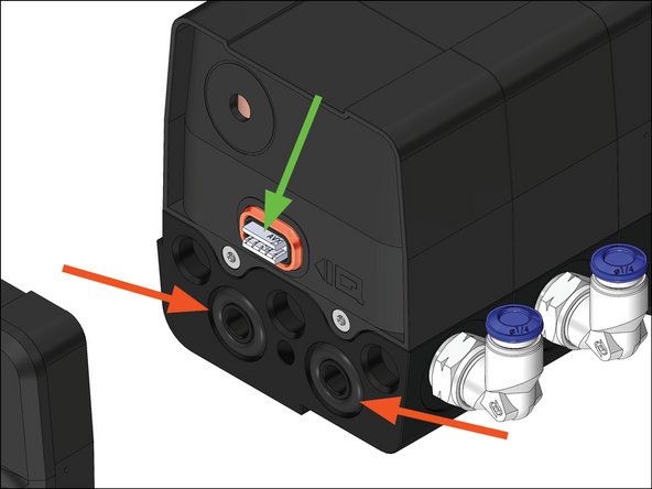
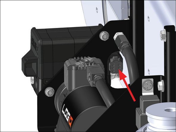
Unplug the harness connector from the AirIQ module by pressing down the tab and pulling out.
-
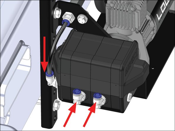
Use a piece of tape to mark the left and right air lines if applicable.
-
Disconnect all air lines from the AirIQ module by:
-
Pressing down on the blue ring of the fitting.
-
Pulling out on the air line.
-
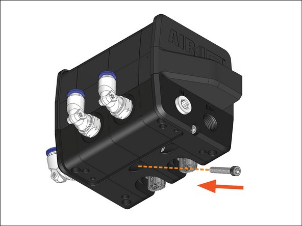
Remove the three or four #10 button head screws holding the AirIQ module to the bracket using a 1/8" hex bit and remove the module.
-
-
-
Remove the #8 socket head cap screw holding the ECU module (module with the elbow fitting) to the Corner module.
-
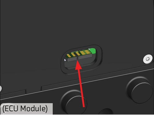
Carefully pull apart the ECU module from the rest of the AirIQ module.
-
-
-
Replace the old O-rings on the Corner module with the supplied ones.
-
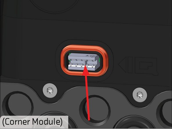
Verify there is a connector in the Corner module, and it is fully seated.
-
As you press on the new ECU module, ensure the connector notches line up.
-
-
-
Carefully press the new ECU module onto the AirIQ module, ensuring the connectors line up.
-
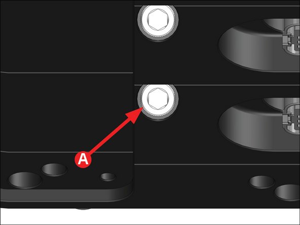
Insert the supplied #8 socket head cap screw into the threaded hole as shown and snug with a 9/64" hex bit.
-
A: Torque the #8 screw to 50 IN. LB.
-
-
-
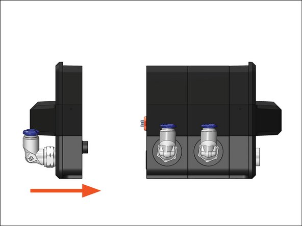
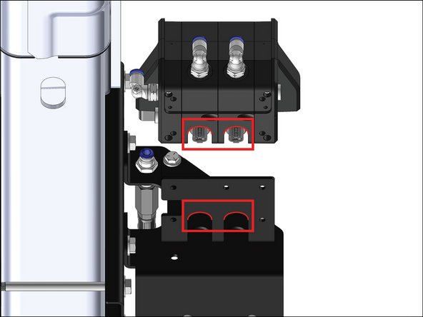
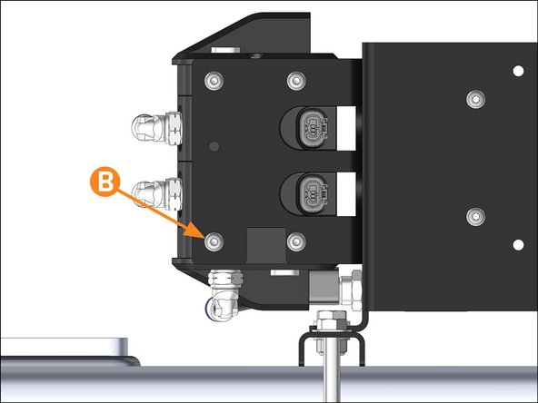
Ensure correct orientation by lining up the radiused cutouts on the module with the radiused cutouts on the bracket.
-
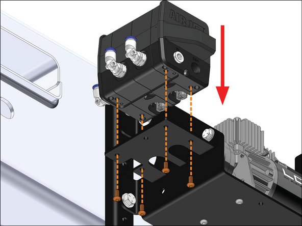
Re-install the updated AirIQ module using the original #10 screws.
-
B: Torque the #10 screws to 25 IN. LB.
-
-
-
Re-connect all air lines to the correct air fittings.
-
Plug in the harness connector to the AirIQ module.
-
-
-
Check for leaks at fittings with soapy water.
-
Verify all fasteners are torqued properly.
-
Check that all electrical connections are fully connected.
-


Congrats! You've successfully replaced your AirIQ ECU Module.
Congrats! You've successfully replaced your AirIQ ECU Module.